Home › Unlabelled ›
Piezoelectric Sensor Circuit Diagram / How to Build a Piezo Knock Sensor Circuit - In this circuit, the led is glowing for a fraction of seconds.
Piezoelectric Sensor Circuit Diagram / How to Build a Piezo Knock Sensor Circuit - In this circuit, the led is glowing for a fraction of seconds.. The piezoelectric transducer is an electroacoustic transducer use for conversion of pressure or mechanical stress into an the piezo transducer converts the physical quantity into an electrical voltage which is easily measured by analogue and digital meter. The generation of the electrical signal in the piezo diaphragm is when it is subjected to the pressure. When a sensor works on the principle of piezoelectricity, it is known as piezoelectric sensor. In this circuit, the led is glowing for a fraction of seconds. Curry, kai ke, meysam t.
Piezoelectric sensors have two output pins one is positive potential and other is at negative potential ( means ground ). While normal operational voltages may be quite small (sound waves in air aren't going to strain the piezo crystal much), the voltages from unintended shocks can easily damage oa1. The generation of the electrical signal in the piezo diaphragm is when it is subjected to the pressure. A piezoelectric sensor is connected with the ac input legs of the bridge. Footstep power generation circuit diagram.
Piezoelectric Sensor Pinout, Working & Datasheet from components101.com Miller iii, avi patel, insoo kim, jianlin feng piezoelectricity is a phenomenon which allows materials to convert deformation into electricity and vice versa (9). Many piezoelectric materials also show electrical effects due to temperature changes and radiation. A piezoelectric transducer (also known as a piezoelectric sensor) is a device that uses the piezoelectric effect to measure changes in acceleration, pressure, strain, temperature or force by converting this energy into an electrical charge. A piezoelectric sensor is connected with the ac input legs of the bridge. Appendix a circuit computation with q. What are piezoelectric pressure sensors? The components required for this circuit are four resistors, speaker, two npn transistor , capacitor, and piezo diaphragm. This heat sensor uses the piezoelectric property to sense heat.
The following circuit shows the piezoelectric sensor circuit diagram.
Curry, kai ke, meysam t. The components required for this circuit are four resistors, speaker, two npn transistor, capacitor, and piezo diaphragm. Computation of node voltages can always be performed. Today i share with you a piezo sensor it is a piezoelectric crystal.i discuss with you a different experiment with a piezo sensor with energy generation in the previous post we discuss stepper motor contro… Where piezoelectricity is a phenomenon where electricity is generated if mechanical stress is applied to a. It is unclear what the designer intended for d1. Here the circuit design of vibration sensor alarm. The positive lead of the knock sensor connects to analog pin a0 of the arduino board and. It is a polarized electronic component, so polarity must be observed in order the above circuit is shown below in a schematic diagram: Initially, when power switch s1 is flipped to on position, power indicator led1 lights up immediately. Appendix a circuit computation with q. A piezoelectric sensor is a device that uses the piezoelectric effect to measure changes in pressure, acceleration, temperature, strain, or force by converting them to an electrical charge. Positive potential pin is connected with pin 3 analog channel of arduino and negative.
To increase the on time of led you can increase the capacitor rating, but it will take more time to charge. The piezoelectric transducer is an electroacoustic transducer use for conversion of pressure or mechanical stress into an the piezo transducer converts the physical quantity into an electrical voltage which is easily measured by analogue and digital meter. Sensing principles of piezoelectric sensors 1. This application note deals with the analog signal conditioning circuit used in shock sensors that behave like piezoelectric sensors. Here the circuit design of vibration sensor alarm.
Charge amplifier for piezoelectric sensors with balanced ... from www.researchgate.net Iepe sensors are used to measure acceleration, force or pressure. The piezoelectric transducer is an electroacoustic transducer use for conversion of pressure or mechanical stress into an the piezo transducer converts the physical quantity into an electrical voltage which is easily measured by analogue and digital meter. A piezoelectric sensor is a device that uses the piezoelectric effect to measure changes in pressure, acceleration, temperature, strain, or force by converting them to an electrical charge. When a sensor works on the principle of piezoelectricity, it is known as piezoelectric sensor. Fortunately, we can easily create a we've discussed the piezoelectric phenomenon in the context of electronic sensor devices, and we saw that a piezoelectric device can be. It relates to all products of the tsx7 and tsx9. Many piezoelectric materials also show electrical effects due to temperature changes and radiation. To increase the on time of led you can increase the capacitor rating, but it will take more time to charge.
A piezoelectric sensor is a device that uses the piezoelectric effect to measure changes in pressure, acceleration, temperature, strain, or force by converting them to an electrical charge.
Today i share with you a piezo sensor it is a piezoelectric crystal.i discuss with you a different experiment with a piezo sensor with energy generation in the previous post we discuss stepper motor contro… This heat sensor uses the piezoelectric property to sense heat. Charge detection sensor resonant sensor ultrasonic wave sensor. Circuit diagram of sensor using arduino, sensor working, specifications, code, and applications. The positive lead of the knock sensor connects to analog pin a0 of the arduino board and. About the piezoelectric transducer or piezoelectric sensor: The following circuit shows the piezoelectric sensor circuit diagram. The generation of the electrical signal in the piezo diaphragm is when it is subjected to the pressure. Footstep power generation circuit diagram. Piezoelectricity is a phenomenon where electricity is generated if mechanical stress is applied to a material. It is a polarized electronic component, so polarity must be observed in order the above circuit is shown below in a schematic diagram: Piezoelectric sensors have two output pins one is positive potential and other is at negative potential ( means ground ). The components required for this circuit are four resistors, speaker, two npn transistor , capacitor, and piezo diaphragm.
Curry, kai ke, meysam t. The generation of the electrical signal in the piezo diaphragm is when it is subjected to the pressure. The following circuit shows the piezoelectric sensor circuit diagram. The positive lead of the knock sensor connects to analog pin a0 of the arduino board and. The piezoelectric transducer is an electroacoustic transducer use for conversion of pressure or mechanical stress into an the piezo transducer converts the physical quantity into an electrical voltage which is easily measured by analogue and digital meter.
Music Device Circuit: piezo sensor | Circuit, Sensor, Music from i.pinimg.com Piezoelectric sensors have two output pins one is positive potential and other is at negative potential ( means ground ). Diagram below shows the hardware connections of piezoelectric sensor interfacing with arduino. Every time the piezo element receives a pdf signal conditioning piezoelectric sensors a piezoelectric sensor is modeled as a. The circuit also functions as a sensitive fire alarm. Computation of node voltages can always be performed. Curry, kai ke, meysam t. Circuit diagram of sensor using arduino, sensor working, specifications, code, and applications. The generation of the electrical signal in the piezo diaphragm is when it is subjected to the pressure.
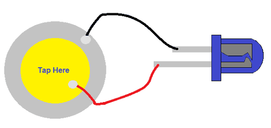
The positive lead of the knock sensor connects to analog pin a0 of the arduino board and.
The two options are voltage sources and current sources. This report is limited to piezoelectricity. Piezoelectric sensors have disadvantages, too. Equivalent circuit of piezoelectric vibrator. When a sensor works on the principle of piezoelectricity, it is known as piezoelectric sensor. Curry, kai ke, meysam t. Piezoelectricity is the charge created across certain materials when a mechanical stress is applied. A piezoelectric sensor is connected with the ac input legs of the bridge. Footstep power generation circuit diagram. Today i share with you a piezo sensor it is a piezoelectric crystal.i discuss with you a different experiment with a piezo sensor with energy generation in the previous post we discuss stepper motor contro… Care is required in the design and implementation of the external electronics. The document explains how to condition a signal coming from a shock sensor and how to improve performance. Circuit diagram of sensor using arduino, sensor working, specifications, code, and applications.